Model PQBS-T-P Type 1

SWL: Up to 30 tonnes
Wheel-drive system: Hydraulic
Quad wheel-drive units: Tilting and adapting to different hull shapes
Slipway operation: Semi-automatic with single-operator
Slipway slope length: According to customers' request
Slipway angle: Up to 12° slope angle
Slipway access/entrance: Via submerged wheel units on vessel transom
Boat guiding system: Tilting quad wheel units
Slipway cradle dimensions: Designed to purpose and vessel interface
Slipway cradle movement: Hydraulic operated cylinders
To/from parking position: By quad wheel-drive units
- Remote control from daughter craft
- Various remote control options on vessel side
- Power and control system redundancy
- Emergency launch by accumulator
- Emergency recovery by accumulator and UPS
- Higher slope angle and/or SWL (if possible/feasible)
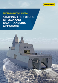
Slipway and stern entry systems with quad wheel-drive units
PALFINGER's hydraulically powered, semi-automatic Slipway System consists of several wheel-drive units (quad units) in two (or multiple) rows that rotate on axes to automatically adapt the slipway to the hull shape of a daughter craft during launch and recovery operations.
A daughter craft can engage the slipways at a range of speeds, up to seven knots higher than the speed of the mother vessel with some systems. When a boat enters the slipway the overrunning clutches allow free rotation of the wheels in the recovery direction until the boat speed and wheel-drive speeds match.
At that point, the hydraulically powered wheel-drive units take over under single-operator control and dock the daughter craft safely inside the slipway. End stoppers automatically set the craft in parking and stowage positions and engage failsafe brakes on the wheel-drives.

MAX. SEA STATE FOR SLIPWAY OPERATIONS
The structural strength of the system is high and is normally not the limiting factor. Test and operational use of PALFINGER Slipway Systems have been performed in Sea States above seven with the mother vessel steaming ahead at low speed.
Safe operations at high Sea States are highly dependent on:
- Mother vessel heading and speed
- Mother vessel responsiveness (RAO Profile)
- Waves and wind pattern
- Boat driver’s skills
QUAD WHEEL-DRIVE UNITS
Wheel-drive unit configuration: 4 wheels on each wheel-drive unit
Brakes: 1 for each wheel
Hydraulic motors: 1 for each wheel
Over-running clutches: 1 for each wheel
Number of quad wheel-drive units: Depending on length of slipway
Length of quad wheel-drive units: 1,526 mm
Width of quad wheel-drive units: 960 mm
Wheel diameter: Ø 600 mm
Wheel-drive units tilt mechanism: 2x Bearing arrangement
Wheel-drive unit tilt range: +/-20°
Max. freewheel speed, inlet: 0-240 m/min (0-7 knots)
Max. freewheel speed, outlet: 0-35 m/min (0-1.1 knots)
Drive assist speed, in and out: 0-25 m/min (0-0.8 knots)
Max. depth for installation: 2 meter below water surface
Max. load, each wheel: 4 tons
Weight (each wheel-drive unit): Approximately 725 kg
Other slipway and stern entry systems
")