- Home
- Deck Equipment
- Slipway and Stern Entry Systems
Slipway and stern entry systems
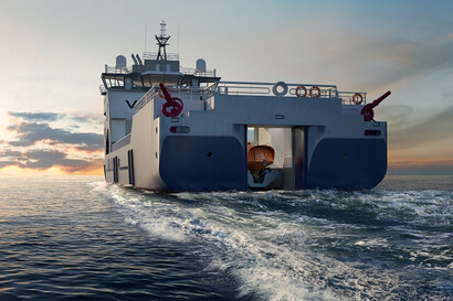
Are you looking for reliable and efficient slipway and stern entry systems? PALFINGER MARINE offers different versions of its Slipway and Stern Entry Systems. To explore our range of Slipway and Stern Entry Systems, browse through the page or click on the links provided on the right-hand side to jump right into the details.
Slipway and stern entry systems with quad wheel-drive units
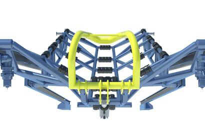
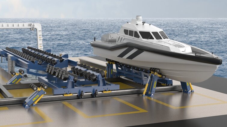
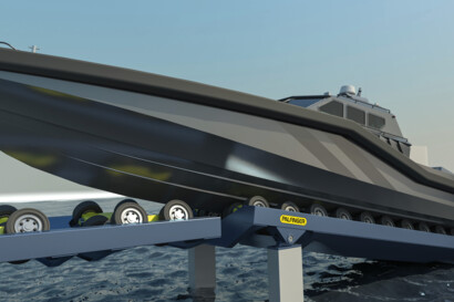
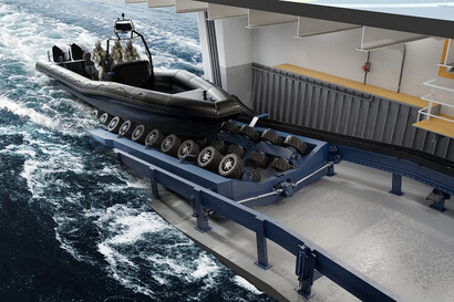
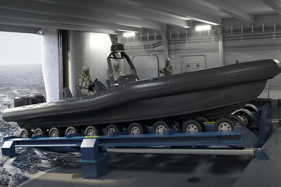
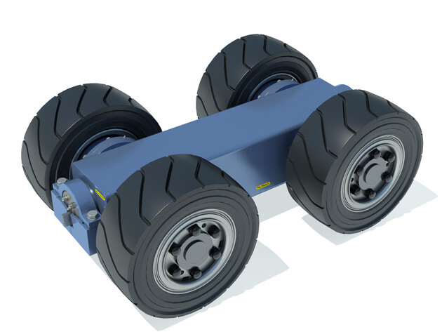
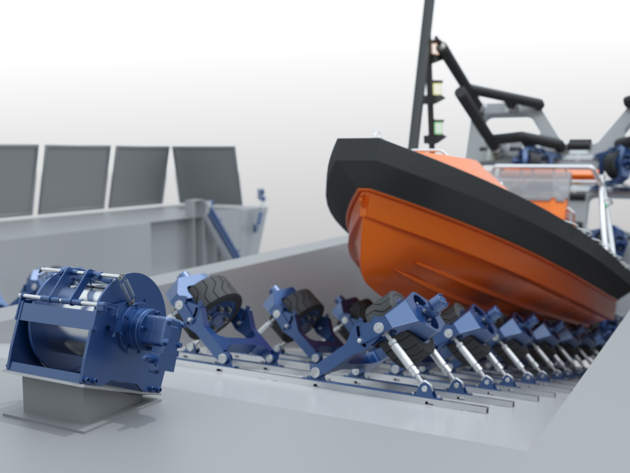
PALFINGER's hydraulically powered, semi-automatic Slipway System consists of several wheel-drive units (quad units) in two (or multiple) rows that rotate on axes to automatically adapt the slipway to the hull shape of a daughter craft during launch and recovery operations.
A daughter craft can engage the slipways at a range of speeds, up to seven knots higher than the speed of the mother vessel with some systems. When a boat enters the slipway, the overrunning clutches allow free rotation of the wheels in the recovery direction until the boat speed and wheel-drive speeds match.
At that point, the hydraulically powered wheel-drive units take over under single-operator control and dock the daughter craft safely inside the slipway. End stoppers automatically set the craft in parking and stowage positions and engage failsafe brakes on the wheel-drives.
The structural strength of the system is high and is normally not the limiting factor. Test and operational use of PALFINGER Slipway Systems have been performed in Sea States above seven with the mother vessel steaming ahead at low speed.
Safe operations at high Sea States are highly dependent on:
- Mother vessel heading and speed
- Mother vessel responsiveness (RAO Profile)
- Waves and wind pattern
- Boat driver’s skills
Wheel-drive unit configuration: 4 wheels on each wheel-drive unit
Brakes: 1 for each wheel
Hydraulic motors: 1 for each wheel
Over-running clutches: 1 for each wheel
Number of quad wheel-drive units: Depending on length of slipway
Length of quad wheel-drive units: 1,526 mm
Width of quad wheel-drive units: 960 mm
Wheel diameter: Ø 600 mm
Wheel-drive units tilt mechanism: 2x Bearing arrangement
Wheel-drive unit tilt range: +/-20°
Max. freewheel speed, inlet: 0-240 m/min (0-7 knots)
Max. freewheel speed, outlet: 0-35 m/min (0-1.1 knots)
Drive assist speed, in and out: 0-25 m/min (0-0.8 knots)
Max. depth for installation: 2 meter below water surface
Max. load, each wheel: 4 tons
Weight (each wheel-drive unit): Approximately 725 kg
Slipway and stern entry systems with single wheel-drive units
PALFINGER’s hydraulically powered, semi-automatic Slipway System consists of several single wheel-drive units in parallel rows. The tilt, height, and distance between the wheels can be manually adjusted to conform to a range of daughter craft hulls.
A daughter craft can engage the slipways at a range of speeds up to seven knots higher than the speed of the mother vessel. When a boat enters the slipway, the overrunning clutches allow free rotation of the wheels in the recovery direction until the boat speed and wheel-drive speeds match.
At that point, the hydraulically powered wheel-drive units will take over under single-operator control and dock the daughter craft safely inside the slipway. End stoppers automatically set the craft in parking and stowage positions and engage the fail-safe brakes on the wheel-drives.
MAX. SEA STATE FOR SLIPWAY OPERATIONS
Test and operational use of this Slipway System have been performed in Sea States 3 with mother vessel steaming ahead with low speed.
Safe operations at higher Sea States may be possible but is highly dependent on:
- Stern entry arrangement
- Mother vessel heading and speed
- Mother vessel responsiveness (RAO Profile)
- Waves and wind pattern
- Boat driver’s skills
SINGLE WHEEL-DRIVE UNITS
Wheel-drive unit configuration: 1 wheel on each wheel-drive unit
Wheel angle and transverse spacing: Manually adjustable
Brakes: 1 for each wheel
Hydraulic motors: 1 for each wheel
Over-running clutches: 1 for each wheel
Number of single wheel-drive units: Depending on length of slipway
Wheel diameter: Ø 434 mm (Foam filled)
Max. freewheel speed, inlet: 0-240 m/min (0-7 knots)
Drive assist speed, in and out: 0-25 m/min (0-0.8 knots)
Max. slipway slope angle: up to 12°
Max. payload for slipway: up to 12 tons
Max load, each wheel: 2 tons
Weight (each wheel-drive unit): Approximately 420 kg
Slipway and stern entry systems with boat cradle
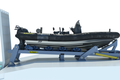
PALFINGER's boat cradle is an open and light tubular steel design, which minimizes forces induced by waves and currents. The boat cradle is supported by mechanical load bearing support/drive rails and wheel/bearing arrangements on both sides of the boat cradle structure.
The inside of the boat cradle is fitted with fenders to protect and guide the water craft during launch and recovery. A weaklink mechanism protects the boat cradle against higher forces than it is designed to withstand. The “bow section” of the boat cradle is fitted with an automatic mechanical securing clamp. The clamp is hydraulic operated and equipped with a quick-lock function.
The stern end of the boat cradle is designed for easy and safe access during launch and recovery and to avoid any conflicts with daughter craft’s drive system. The system is also well suited for handling of crafts with multiple outboard engines or stern drives.
BOAT CRADLE DRIVE SYSTEMRails on each side of the boat cradle serve as guide and support mechanisms for the boat cradle while it is travelling up and down the slipway slope. One of the guide rails on each side of the slipway slope is fitted with a tooth rack for the drive system.
Longitudinal movements and heave/lowering of the boat cradle is done by hydraulic powered pinion drives mounted on each side of the boat cradle. The hydraulic pinion drive motors are fitted with automatic overrunning clutches, allowing residual energy from the water-craft to be transferred into forward motion of the boat cradle in case the water-craft is approaching the boat cradle with excess speed.
BOAT CRADLE ELEVATOR
Vertical movements are driven by the two mechanical support and guide rails on each side of the boat cradle. The mechanical support and guide rails (located on the stern of the vessel) guide the boat cradle to the horizontal parking position when the boat cradle is retracted by the rack and pinion drive system.
MAX. SEA STATE FOR SLIPWAY OPERATIONS
Test and operational use of this Slipway System have been performed in Sea States 3 with mother vessel steaming ahead with low speed.
Safe operations at higher Sea States may be possible but is highly dependent on:
- Mother vessel heading and speed
- Mother vessel responsiveness (RAO Profile)
- Waves and wind pattern
- Boat driver's skills
SAFE OPERATION
- No need for lifting, hooking, mechanical connection or use of painter lines and arrester wires during launch and recovery operations
- Significantly reduced risk of accidents during operations
- Implementation of close guiding in all phases of launch and recovery reduces the risk of damage and accidents caused by collision between daughter craft, mother vessel, and handling equipment
- No need for manual support or interaction from the boat crew during launch and recovery
CREW AND PASSENGER COMFORT
- Safe, comfortable, and easy launch and recovery operations, even in harsh weather conditions
- Wheel-drive units ensure very harmonic and “gentle” load distribution to the boat hull, which ensure a smooth and seamless transition in and out of the slipway
- Rubber drive wheels protect the hull of the daughter craft, extending its lifetime
UNMANNED CRAFTS
- Slipway systems can handle unmanned crafts such as Unmanned Surface Vehicles (USV’s) and Autonomous Underwater Vehicles (AUV’s)
OPERATIONAL ENVELOPE, SYSTEMS PERFORMANCE AND SPEED
- No need for complex tasks and highly coordinated efforts from multiple crew members during launch and recovery operations, increasing safety as well as the operational weather envelope and speed of operations
- Single-operator Slipway Systems are easy and intuitive to use; vessel personnel can become proficient operators in a short period of time
VERSATILITY
- Slipway Systems can handle crafts with different hull shape, propulsion system, and weight
- Slipway Systems can handle multiple crafts and transfer crafts from the slipway to a stowage position on the mother vessel
RULES AND REGULATIONS
- Slipway Systems are normally not categorized as lifesaving equipment. As such, certification and inspections regime in accordance with SOLAS rules would normally not be applicable
- As the system eliminates the need for lifting of free-hanging loads, certification and inspections regime in accordance with rules for lifting appliances would normally not be applicable
DAUGHTER CRAFT RANGE
- Patrol boats
- Rigid inflatable boats
- Fast rescue boats
- Crew transfer boats
- Work boats
- Daughter crafts
- Lifeboats
- Unmanned surface vehicles
- Underwater vehicles
- Autonomous water vehicles
- Special water vehicles
- Catamarans
VESSEL RANGE
- Navy vessels
- Coast guard vessels
- Offshore vessels
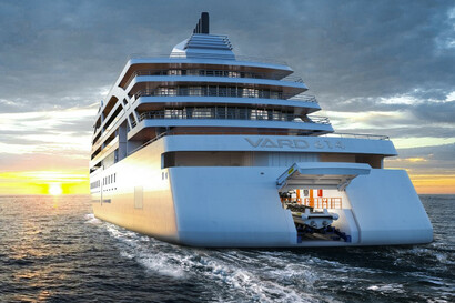
- Expedition cruise vessels
- Offshore fish farm vessels and installations
- Wind farm service operation vessels
- Government and law enforcement vessels
- Special vessels and offshore installations
APPLICATION RANGE
- USV operations
- Patrol and interception
- Shuttle services
- Standby and rescue
- Oil recovery
- Lifeboat recovery
- Crew transfer
- Military operations
- Cruise expedition operations
- Operations on/off unmanned vessels
- Operation of unmanned water crafts
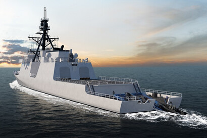
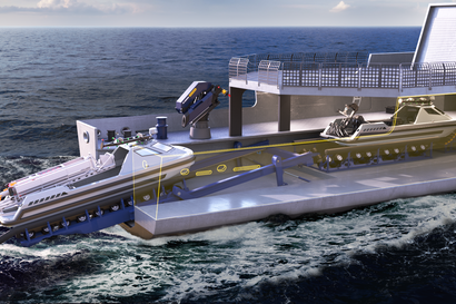
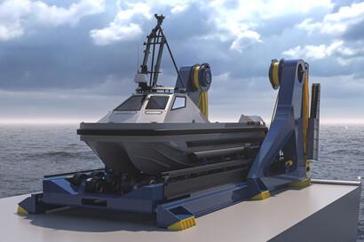
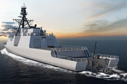
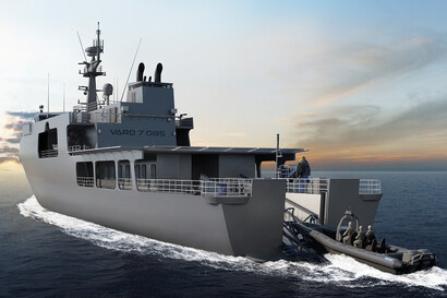
Mission Bay Handling Solution
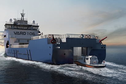
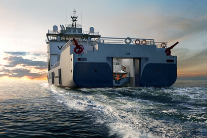
The Mission Bay Handling Solution is fully compatible with our proven Slipway System technology, ensuring reliable performance and seamless integration for demanding naval applications.
 Model: PQBS
  Model: PQBS-T
  Model: PQBS-T-P Type 1
  Model: PQBS-T-P Type 2
  Model: PQBS-D
  Model: PQBS-D-P
  Model: PQBS-D-S
  Model: PQBS-T-D-P
  Model: PQBS-D-C
  Model: PQBS-R
 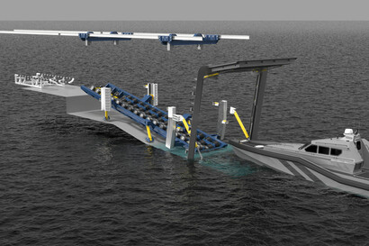 Model: PQBS-SR-E-P
 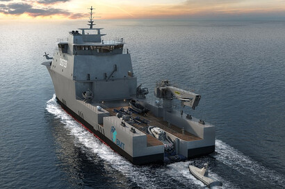 Model: PQBS-E-P
 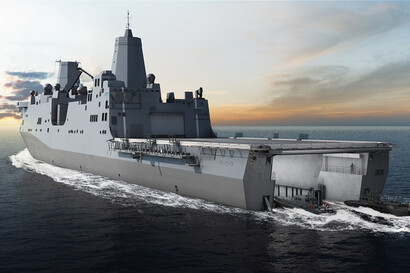 Model: PQBS-MB-B
 Model: PSWS-SR
  Model: PSWS-T-D
 Model: PSEC